
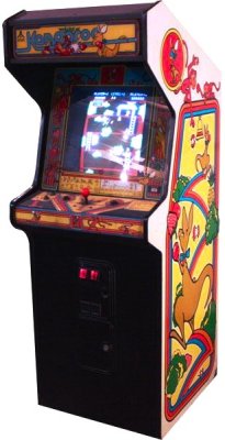
Kangaroo
Texts
| Developer |
SunSoft |
| Publisher |
Atari (1972) |
| Release |
1982 |
| Dimensions |
64×81×180cm 138kg |
| Also for |
Atari 2600, Atari 5200 |
| Edition |
US |
|
|
|
|
|
 |
Options are preset at the factory and shown by the * symbols.
SETTINGS of 8-Toggle Switch on
Kangaroo CPU PCB                Option
----------------------------- 	-----------------------------------------------
1   2   3   4   5   6   7   8
0                               3 Kangaroo Lives *
1                               5 Kangaroo Lives

    0                           Easy game difficulty *
    1                           Hard game difficulty

        0   0                   No Bonus Kangaroos
        1   0                   Bonus Kangaroo at 10k
        0   1                   Bonus Kangaroo at 10k, 30k, and every 30k after
        1   1                   Bonus Kangaroo at 10k, 40k, and every 40k after

                                Left Coin Mechanism     Right Coin Mechanism
                                Games with one counter  Games with two counters
                0   0   0   0   1 coin  for 1 credit    1 coin  for 1 credit *
                1   0   0   0   2 coins for 1 credit    2 coins for 1 credit
                0   1   0   0   1 coin  for 1 credit    1 coin  for 3 credits
                1   1   0   0   1 coin  for 1 credit    1 coin  for 2 credits

                0   0   1   0   1 coin  for 1 credit    1 coin for 3  credits
                1   0   1   0   1 coin  for 1 credit    1 coin for 4  credits
                0   1   1   0   1 coin  for 1 credit    1 coin for 5  credits
                1   1   1   0   1 coin  for 1 credit    1 coin for 6  credits

                0   0   0   1   1 coin  for 2 credits   1 coin for 2  credits
                1   0   0   1   1 coin  for 2 credits   1 coin for 4  credits
                0   1   0   1   1 coin  for 2 credits   1 coin for 5  credits
                1   1   0   1   1 coin  for 2 credits   1 coin for 10 credits

                0   0   1   1   1 coin  for 2 credits   1 coin for 11 credits
                1   0   1   1   1 coin  for 2 credits   1 coin for 12 credits
                0   1   1   1   1 coin  for 2 credits   1 coin for 6  credits
                1   1   1   1   Free play               Free play

* indicates the Manufacturer's recommended settings

SELF-TEST PROCEDURE

To perform the self-test procedure, set the self-test switch to ON or
simultaneously power the game ON and press the service switch. To end
the self-test, set the self test switch to OFF. (The Service Switch is
a round button on the upper right corner CPU board to the left of the
dip switches. FWIW, It looks like the Test Switch grounds the test
signal from CPU board pin J to the ground pin V)

   NOTE: This procedure does not test the coin door lockout coils. If the
   Self-Test passes, but the lockout coils do not energize when power is
   applied to the game, suspect the lockout coil wiring, coin door
   harness, game PCB harness, or transistor TR3 (for the Ireland-Built
   cabinet check TR3 and TR4) and related circuitry of the CPU PCB.

SELF-TEST SCREEN 1

When the self-test switch is set to ON, the screen shows the self-test
display. The ROMs and RAMs are tested at this time.
The Self-Test screen looks like this (comments are in lower case).

		  cocktail only
		punch	joystick

			    0

		    0    0  *  0

			    0

color	      ****  ****  ****  ****  ****  ****  ****
adjustment    ****  ****  ****  ****  ****  ****  ****
chart	      ****  ****  ****  ****  ****  ****  ****
	      ****  ****  ****  ****  ****  ****  ****

					edge connector settings (see below)

switch      	 DIP  1 2 3 4 5 6 7 8	3A 	3B 	4A 	8A
settings
		      0 0 0 1 0 0 0 0    1	 0	 1	 1

service	   S	0				C1	C2
							     right & left
player 1   1	0	   1			0	0    coin mechs
start

player 2   2	0	1  *  0	   0 		  SOUND	     sound test
start
			   0			    2

			joystick   punch
			player one, or upright

The COLORS from left to right are BLUE, GREEN, LT. BLUE, RED, VIOLET,
YELLOW, and WHITE.

Activate all SWITCHES on the control panel, coin mechanisms, and
the service switch (located on the upper right of the CPU board
to the right of the DIP switches). The test changes 0 to 1 as the
switch is activated.

SWITCH FAILURE is indicated by the proper 0 or 1 not changing on the
screen when the switch is activated.

(Kangaroo requires an eight-way JOYSTICK, which signals diagonal
movements by allowing two adjecent switches to close at once.)
Push the joystick(s) diagonally up and to the left. For proper
game operation, both the top and left switches MUST close at the
same time, and the top and left 0s should each become 1 (as shown
above). Push the joystick diagonally and to the right, repeating
the same procedure. Both the top and right switches should close,
changing the corresponding 0s to 1s on the screen.

The EDGE CONNECTOR SETTINGS represent harness connections on the CPU PCB.
1 means the pin is shorted to ground in the harness
0 means there is no connection in the harness.

		Screen		Pin on CPU
		Shows	    Harness Connector

		 3A		   C
		 3B		   3
		 4A		   D
		 8A		   J

NOTE	8A is a zero if you enter self-test mode by pressing
	the service switch on the CPU PCB (while turning the
	machine on, as opposed to using the test switch on
	the utility panel.)

ROM FAILURE is indicated on the screen by the words ERROR ROM- and a
number (for a ROM failure on the CPU PCB), or the words ERROR ROM V-
and a number (for a failure on the Video PCB). The following lists the
ROM chips and their locations.

				Bad ROM Chip Location
	Screen Display			CPU PCB

	ROM-0  *			IC7
	ROM-1				IC8
	ROM-2				IC9
	ROM-3				IC10
	ROM-4				IC16
	ROM-5  *			IC17
	ROM-8  *			IC24
	ROM-12 *			IC28

					Video PCB
	ROM V-0				IC76
	ROM V-1				IC52
	ROM V-2				IC77
	ROM V-3				IC53

	* Does not display on the screen if defective

RAM FAILURE is indicated by a blank screen or by garbage displayed on
the screen for a defective RAM at IC5 or IC6 on the CPU PCB. Make sure
that ROM-0 and ROM-5 are good on the CPU PCB. In addition, inspect the
dynamic RAM on the Video PCB at locations IC55-62, 66-73, 79-86 or
93-100. Troubleshoot using the game schematics and the CAT Box (using
a Z80 interface) or a bus controller to locate the failing RAM.

To test the SOUND, simultaneously press the Player 1 and Player 2 start
switches. Game sounds are produced and incremented automatically from SOUND 1
through SOUND J.

	Game Sounds:

	SOUND 1	Game meoldy
	SOUND 2	Kangaroo jumping
	SOUND 3	Kangaroo punching
	SOUND 4	Kangaroo falling

	SOUND 5	Kangaroo dying
	SOUND 6	Apple falling
	SOUND 7 Kangaroo punching and apple or gorilla
	SOUND 8	Bonus Kangaroo awarded

	SOUND 9	Begin new level
	SOUND A	Monkey dying
	SOUND B	Kangaroo getting fruit
	SOUND C	End of level

	SOUND D	Bell ringing
	SOUND E	Monkey column decreasing by one monkey
	SOUND F	Gorilla taking Kangaroo's gloves
	SOUND G	Kangaroo crouching

	SOUND H	Apples falling from broken branch
	SOUND I	Kangaroo climbing ladder
	SOUND J	Kangaroo hopping

SOUND FAILURE is indicated by no sound. Check the volume control
levels on the utility panel and on the CPU PCB at VR2. Troubleshoot
the following sound circuitry on the CPU PCB: G.I. sound chip at IC50,
ROM 8 at IC24, Z80 Microprocessor at IC34, RAMs at IC32 or 33, or
audio amplifier at IC61.

To go to screen 2, push the 1-player start and either PUNCH switch at
the same time.

SELF-TEST SCREEN 2

A white crosshatch pattern with white dots centered in each square
appears on the screen. (The grid is enclosed by a red rectangle.) The
center part of each side of the red rectangle should be 1/4 inch
behind the bezel, out of view. Use this pattern for convergence and
white balance.


 copyright